An electrathon vehicle is an electric vehicle with at least three wheels. It is similar in size to a go-kart (maximum 100 and 80 inches). Its weight cannot exceed 100 pound. Unlike a go-kart, it is powered by an electric motor and lead-acid battery, industrially produced.
This type of lightweight car appeared in Australia in the late 1970s and was warmly embraced and introduced into American culture as early as 1980.
Electromarathon contest
An Electrathon is a type of marathon in which the winner is determined by the distance covered in a given battery time. Electrathon competitions adopt specific design rules to ensure a safe and fair competition. Electrathon competitions are held across the United States and are considered a progressive and environmentally friendly new sport.
Using limited electrical power, electric cars travel as much distance as possible on a closed track in one hour.
Provides an opportunity to demonstrate, compare and test skills and ingenuity.
Increase public awareness and understanding of efficient electric vehicle alternatives.
More and more participants are coming to the sport. A sport based on fixed rules in which groups and individuals can compete safely. There are other types of electric marathons such as Road Rally, F/EX, Electron Run and Electrathon events. These should not be confused with Electrathon of America events.
Electrical engineering marathon sections
The CT Electrathon was launched in 2004, one of the first programs to incorporate education, and it was an innovation. Classes were created due to growing interest and the introduction of new vehicle types. There are three classes: beginner, classic and compound. This allowed new entrants to get the best experience and allowed serious competitors to compete fairly against each other.
The Novice (beginners) class is for school cars that are competing for the first or second time in the Electrathon series and that cannot be composite cars. If a car in the Novice class completes more than 100 laps in its first race, it will be promoted to the Classic class for the next race.
The CLASSIC class includes metal or kit cars if the team has competed with this car in previous events.
The COMPOSITE class is designed for advanced cars without chassis made of composite materials such as fiberglass.
How did it start?
CT Electrathon began in 2001 with the first CT Electrathon Challenge held at Lime Rock Park in Lakeville, Connecticut. The CT Electrathon Challenge was created by the University of Central Connecticut and RHAM High School as part of the CT Electrathon Challenge program was created after hearing about an event called “Big Alternative Energy” to incorporate more research and engineering into the high school environment. The program has grown steadily by 20% each year, and with Lime Rock providing a track twice a year, we hope to see continued growth. The program has grown to include not only schools from Connecticut, but also from the US and Canada. Many of these schools have also started Electrathon events in their states.
Build your own electric car for the electromobile and become a participant of the marathon
If, you have decided to implement an Electrathon project. Like any big project, it is best to break it down into doable parts. The first step is to learn as much as possible about the Electrathon.
The Electrathon America rules book contains diagrams and diagrams and design tips.
Teams usually receive these rules at registration and the Electrathon America rulebook. Designate one or more people who have read and are familiar with the rules.
This will help you design and build your electric marathon car.
Other sources of information are books about karting and electric cars and local racing teams.
You can also find information about local racing teams. Do your research online or talk to people who have raced electric cars.
Do your research online or talk to people who have raced electric cars.
Size and weight
First, let’s calculate the size and weight of your car: your car has a driver weighing 180 pounds and a battery weighing 64 pounds.
We have a battery that weighs 64 pounds. That’s 244 pounds. The weight of the rest of the car is probably
The rest of the car probably weighs 100 to 150 pounds. This means that the wheels and frame must be able to support 350 to 400 pounds.
It must be able to support 350-400 pounds. To compete, a car must weigh less than 130 pounds, not including the driver and battery. For example, the national record holder electric marathon car weighs 90 pounds. Remember the K.I.S. theory, KEEP IT SIMPLE and it will help save on weight.
The dimensions should be as small as possible without compromising safety and manoeuvrability.
This not only reduces weight, but also reduces air resistance. Consider aerodynamics to minimize wind resistance.
Sketch your electric car
The front should be narrow enough and not too tall. It is very tempting to design the body first and then try to cram everything you need into it.
It’s tempting to design the body first and then try to fit everything you need into it, but then you have to change a lot of things when building the chassis.
However, this can be a problem later on when building the frame. On race day you need to have access to everything in the car when you drive into the pits.
On race day, you must have access to everything in the car during pit lane. You don’t want to make a 20-minute pit stop to pull up the battery cables.
You don’t want to make a 20 minute pit stop to pull the battery cables.
Vehicle installation
Let’s simulate a car setup. Have someone sit on the floor and assume a driving pose on the book.
Put some books at a suitable height and ask them to sit on them in the riding position. Bicycle wheels (not really used, they are used for riding).
Bring the wheel of the bicycle to an approximate position. Battery (modeled out of cardboard) and motor (modeled out of a 1-2 pound coffee can). Try to get them to move. It’s easy, quick and doesn’t cost anything.
There are a few things to keep in mind
- Balance the weight. Balance the front, rear and sides. Make sure that each wheel has its own role.Make sure that each wheel has its own function.
- Place all electrical components close together and keep cable lengths short. This will reduce electrical resistance (losses).
- Make sure the driver has enough room to ride comfortably for an hour.
Now take a picture of this installation from all possible angles.
Another way is to put a roll of paper behind your installation and shine a bright light on it, and trace the shadows that appear.
Making the frame
Let’s move on to the next step.
From this point, the wheels touch the ground and support the frame, and the frame supports everything else. Next, it all depends on how you connect the dots. Imagine a rough frame on which the wheels are supported.
Think about what you want to place on the frame. Mount the rollbar on it (there are standard requirements for the rollbar). It is important that the driver, motor, battery, controller and other elements do not touch the ground. Then install the mount. The various elements of the frame must perform two functions. The rollbar can be used as a controller.
Build the frame with aerodynamics in mind. Many electric marathon participants use aluminum to build their frames. Aluminum is strong and lightweight, but expensive. You can try to find aluminum tubing at your local muffler shop.
If the frame is strong enough and complies with the rules, wrong moments are not foreseen.
Be creative and have fun doing it. In all these initial plans
Follow the rules of brainstorming.
- Introduce all ideas, no matter how strange they may seem.
- Don’t criticize other people’s ideas. A strange idea may lead to another idea. It may even become your idea.
- Write down all ideas and systematize them for the future.
When designing the frame, consider the strength of the triangular section and the corner joints.
When designing the frame, consider the strength of the triangular section and the corner joints. Leave room to add reinforcement if necessary.
Wheels
It’s standard to have two wheels at the front and one at the back.And according to Electrathon America rules, an EV must have at least three wheels.
The only advantage of four wheels: with three wheels there is less air and mechanical resistance and less need for suspension.
The need for suspension is also less. The need for suspension arises from the torsion of the chassis of a four-wheeled vehicle.
The need for suspension arises from the torsion of the chassis of a four-wheeler: three wheels are always in contact with the road surface, whereas four wheels are always in contact with the road surface unless the track is completely flat, especially on bends.
A three-wheeled design is more accurately described as a rear three-wheeled design (velomobile). On tight corners and when braking, the weight ratio on the front wheel changes. The weight ratio on the front wheel increases (because the front fork of the electric car compresses). At the same time, the handling of the vehicle changes.
If the change in steering is too great, the vehicle can tip over when only one front wheel is engaged. This does not happen in all cases, but in most cases.
Some of the cars you’ll see at the Electric Marathon have three wheels.
You can buy wheels or assemble them. We do not recommend the use of standard bicycle wheels. It is best to use moped or BMX wheels.
Talk to your local bike shop (these shops are a great source of information) about what you do and what you need. They may be able to make a custom wheel for you. They might even be able to make a special wheel for you at a discount (remember, if they help you, consider them a sponsor and put a sticker on it).
Tell them that these wheels are subject to lateral and vertical loads. In the case of bicycles. Bicycles are always subject to vertical loads, even when cornering, due to the fact that the bike leans into the corner. The wheels are set aside and the wheels of a regular bicycle are folded. This makes it unsafe for you and all other road users.
Steering
Steering is one of those areas where it’s hard to spell out exactly what’s best for your car.
On the one hand, steering turns the steering wheel to steer the vehicle. On the other hand, it imposes certain obligations on the driver. We recommend looking at cars, garden tractors, go-karts and preferably other electric vehicles.
Look at everything you can to get an idea of what others are doing in terms of steering tips and wheel supports. Look as much as you can to get an idea of what others are doing with knuckles.
Example of a marathon electric car development
If you’ve already decided to go further, the hands-on example of Zack and Joe, who seriously designed an electric car, may give you ideas.
In order to verify the ergonomic feasibility of the frame design, a full-scale mock-up of the PVC frame was made. This diagram shows that the frame elements in the shoulder area are too narrow and the arch needs to be raised. Two racers, John and Hunter, had to test the updated chassis design, and the choice of 6061 T1 aluminum required careful analysis of the chassis and safety frame in ANSYS. Driver protection in frontal, side and rollover crashes was a top priority in Zack’s frame design analysis. The safety factor for frontal and side impacts was 6, and for rollover it was 14. The industry standard for cars is a safety factor of 5.
After checking the frame elements on the drawing, Zach started cutting and shaping the aluminum tubes on the assembly table. The main frame material is 1″ outside diameter and the side impact components are made from 1-1/4″ outside diameter tubing. Zach was responsible for the TIG welding on this project. John and Hunter set up a milling machine to cut a “fish mouth” connection in the end of the tube. Each joint had to be individually beveled to match the angle of the adjacent tube. Joe (left), John and Zach discuss the frame layout for the engine mounts and rear wheel outlets. The frame elements will now be stitched together and bolted to the mounting table.
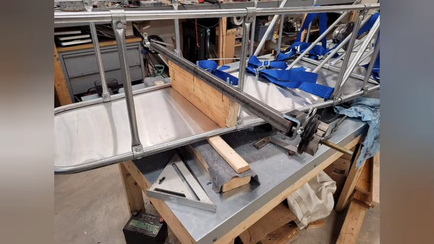
Cutting the right length of aluminum tubing, the right angle for the fishmouth joint, the rectangular shape, and welding the frame took a long time.
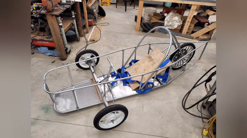
When the basic framework is complete, we feel that we have reached an important milestone. It’s easy to get many of the remaining details wrong. It’s time to consider some of the ergonomic changes made to the design. Note the extended side supports on the shoulders and the raised crossmember. Now it’s time to build and assemble the front suspension and steering, transmission and rear wheels, seats, battery compartment, solar panels and body panels.
The position of the front wheel is already determined by the frame support. The wire spokes used in the bike rims are not designed for lateral loads during fast cornering. It was necessary to incorporate negative camber into the front suspension. Part of this cam was achieved by the original front suspension setup. John designed the front suspension to be “double wishbone isometric rather than parallel,” allowing for a more “dynamic” negative camber. When the car tilts in a corner, the extra load on the outer wheel creates an extra 3° of negative camber. The A-arms are identical at the top and bottom, so they are easy to fabricate with a welding machine. The A-arm mounting brackets are made from 6″ x 2″ square tube The original mounting points were adjustable. The original mounting points were adjustable. I decided on the angle of the roller and welded the mounting bracket to that angle. Fine tuning the wheels and camera can be done by turning and unwinding the hinges. You can also use the A-arm mounting bracket to make a shock absorber mounting bracket, which can then be welded on. This bracket is designed to fit the 700 lb mountain bike “coil-over shock” shock absorber selected for this suspension system. The steel hub support plate and A-arm mounting hinges were fabricated, and their installation confirmed the suspension geometry. Shock absorber mounting brackets can also be fabricated and welded. This bracket is designed to fit the 700lb mountain bike coilovers selected for this suspension system. A steel hub support plate and A-arm mounting hinges were fabricated to verify suspension geometry. Shock absorber mounting brackets can also be fabricated and welded. This bracket is designed to fit the 700 lb mountain bike coilovers selected for this suspension system. A steel hub support plate and A-arm mounting pivots were fabricated and their installation confirmed the suspension geometry.
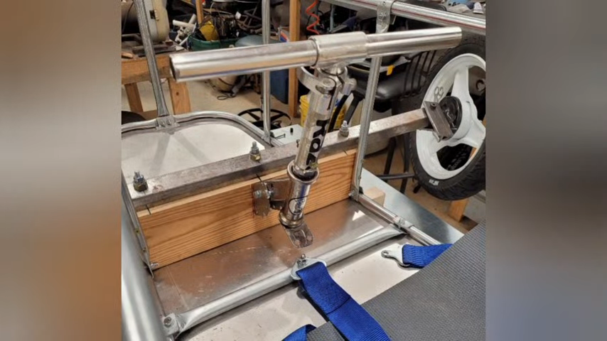
The steering column bracket, steering column pivot point, connecting rod and rods have been machined and welded in place. The initial position of the battery is shown in this diagram. The battery was then moved to an area behind the driver’s seat to relocate the CT. The steering column was deliberately left long until the driver’s seat ergonomics were established.
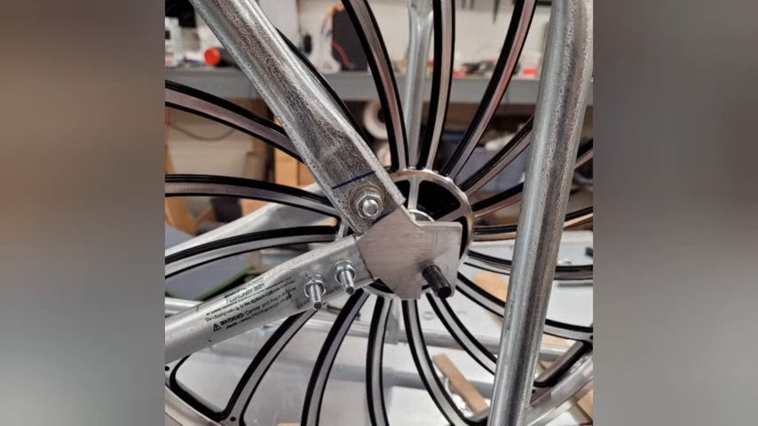
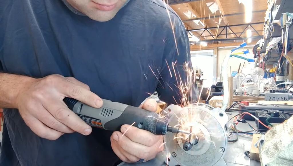
The tubes of the engine control unit and the rear axle recesses are welded. The engine mount bases are also welded to the subframe tubes. The carrier frame tubes have been aligned to correct any small bends that may have occurred during welding. The dropouts also need to be perfectly aligned to the ground, so Zach designed an eccentric that adjusts so that the rear axle is always perfectly perpendicular to the centerline of the vehicle, even with the bike’s normal rear axle dropout. The eccentric is also responsible for creating the necessary tension in the chain. The adapter is made to fit a 12-tooth downward facing sprocket for standard ANSI #40 bicycle chains. The sprocket attaches to the motor shaft; a 22-tooth front clutch combines with a 48-tooth front sprocket to ensure proper sprocket ratio. A 1/4″ aluminum adapter plate is machined and bolted directly to the freewheel clutch. Mounting holes were drilled for direct attachment to the freewheel clutch, and a centering tab was machined on the surface of the adapter plate to fit the chainring.
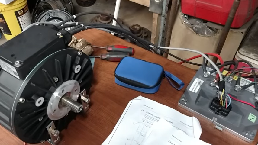
The pulse width modulated controller, which he designed and built himself, performed well during several weeks of testing and competition. An assembly of a commercially available motor controller is shown below. One of the goals of this project was to demonstrate that local high schools could build such a vehicle, but it seemed unlikely that they would make their own motor controllers. A commercially available controller of this type would have been a viable option for the school project. We also placed the battery behind the driver’s seat; this change in weight distribution was necessary to achieve the stable understeer characteristics typical of three-wheeled vehicles.
For the motor controller, Joe, once the board was designed, built a full-scale schematic to test the traces and make sure each component matched the PCB. Once the PCB was delivered, the components were soldered together and prepared for testing. The diagram above shows the “control board” and the diagram below shows the “power board”.
When the assembly was completed, it was time to start testing. Once the body panels were in place, we were able to make the necessary modifications.
A 0.024 inch thick aluminum plate was formed for the rear and side panels, and each panel was clamped to test the fit. The rear panel, battery cover, and solar panel in this image are mounted using DZUS brackets. These mounts provide quick access to the drive system and battery, and the dzus mounts can be used to mount the lexan top cover. The rear cover is fixed with the same dzus brackets as the rear panel.
The Lexan polycarbonate cover (shown above with the protective cover) is secured in place, ready to install the zoned brackets for the rear side cover. Polycarbonate is used for this part of the back cover in order not to damage the telemetry unit mounted high up in this area.
The on-board telemetry and measurement unit contains an Arduino microcontroller board and an XBee transceiver. Thus, the information was connected to the driver’s dashboard and the pit. The cockpit display was mounted on the steering wheel, directly in front of the driver. A 9-pin D-sub connector at the bottom provided a direct connection between the display and the telemetry unit. A button underneath the LCD adjusts the brightness of the display.
We made changes to the nose section. Hunter is the taller of the two drivers, so he needed more legroom. He also needed space to fit a maximum power solar panel tracker. Both of these were solved by lengthening and bending the safety frame tubes and welding them to the extended lower tubes. The aluminum sheets were then laminated and riveted to the nose extension tube. Brackets were also welded to the probe mounts to attach the solar panels. The aluminum plates for the solar panels were also prepared for transportation on an open trailer.
After installing all the panels (except the solar panels) we were able to do a full 1-hour test. Even without the solar panels installed, the 1-hour test (without driver change) gave much better results than in autumn 2011. The team was satisfied with these figures.
After making some changes to the engine controller (changing the throttle speed), both the electrical and mechanical systems worked perfectly. Naturally, it was time to paint the car and apply vinyl lettering.
Registration on the official websites
Check out the upcoming marathon schedule and register at the following sites.